
KT200 Plus Delphi CRD3 Programming Guide: Bench, Backup, Cloning and Recovery
Delphi CRD3 describes a broad family of diesel engine control units rather than one universal controller. A professional KT200 Plus Delphi CRD3 workflow should begin with the complete CRD3 variant, physical ECU identification and exact protocol verification before power, reading or writing is attempted.
Different CRD3 variants may use different hardware, software, processors, memory configurations and programming procedures. Never select a protocol or donor ECU from the general CRD3 name alone.
What Is the Delphi CRD3 ECU Family?
Delphi CRD3 controllers are diesel engine-management ECUs. Depending on the exact version, the ECU can contain operating software, calibration data, configuration information and vehicle-specific data distributed across one or more memory regions.
The CRD3 designation includes numerous variants. A difference after the decimal point or letter suffix can indicate a different hardware or software platform.
The current KT200 Plus protocol database displays the following CRD3-series models:
Identify the Exact CRD3 Before Programming
Photograph the complete ECU label before removing connectors or preparing Bench power. Record every visible identifier rather than copying only the large CRD3 family name.
| Identification item | Why it matters |
|---|---|
| Complete CRD3 designation | Separates variants that may use different protocols and memory layouts. |
| Delphi part number | Helps identify the physical hardware platform. |
| OEM part number | Connects the controller with its original vehicle application. |
| Hardware number | Important for donor selection and file compatibility. |
| Software number | Helps verify original, modified and recovery files. |
| Calibration number | Can distinguish software intended for different engine configurations. |
| Processor or MCU | Determines processor-level access and memory organization. |
| Vehicle and engine | Helps confirm the application when similar ECUs exist. |
Keep the ECU label photograph with the customer files. If identification changes after programming, the physical label remains an important original reference.
Search Delphi CRD3 in the KT200 Plus Database
Use the official KT200 Plus Supported Vehicles and Protocol Database before assembling cables, opening the ECU or loading a file.
Recommended search process
- Search the complete CRD3 variant.
- Compare the Delphi controller family.
- Check the processor or MCU where listed.
- Compare vehicle and engine information where available.
- Confirm the available Read function.
- Confirm the available Write or Clone function.
- Check the required OBD, Bench, Boot or JTAG mode.
- Open the diagram belonging to the exact protocol.
If the full suffix produces no result, search a shorter CRD3 term and inspect the family group. Do not select the nearest-looking result without confirming the actual hardware.
The KT200 Plus Protocol Search Guide explains how to combine the ECU family, processor, vehicle and programming mode when narrowing results.
Choose the Correct Programming Mode
The appropriate programming method depends on the exact CRD3 variant and operation shown in KT200 Plus. No single access method should be assumed for the entire family.
| Mode | Connection | Typical purpose | Main check |
|---|---|---|---|
| OBD | Vehicle diagnostic connector | Supported identification, Virtual Read or writing with the ECU installed | Confirm the exact controller and available operation. |
| Bench | Direct connection through the external ECU connector | Controlled ECU access outside the vehicle without automatically opening it | Verify every power, ground, ignition and communication pin. |
| Boot | Direct connection with board-level processor access | Deeper memory access or supported recovery | Confirm the processor, Boot point and power sequence. |
| JTAG | Dedicated processor or circuit-board points | Direct memory communication on supported hardware | Use the exact adapter orientation and controller diagram. |
Delphi CRD3 Bench Preparation
Bench programming creates a controlled workshop environment, but only when the power and communication connections are correct.
Required preparation
- KT200 Plus software and compatible interface
- Correct controller-specific Bench cable or adapter
- Official connection diagram for the selected protocol
- Regulated workshop power supply
- Digital multimeter
- Reliable Windows computer
- Stable USB connection
- Secure file-backup storage
Connections to verify
- Permanent positive power
- Ground terminals
- Ignition or switched supply
- CAN High and CAN Low
- Secondary communication or wake-up connections where specified
- Connector viewing direction
- Cavity numbering
- Adapter orientation
Check every connection with external power removed. Do not use a resistance or continuity test on an energized ECU circuit.
Power-Supply Verification
A correct voltage shown on the power supply with no ECU load does not prove that the controller receives stable voltage during identification or programming.
Measure directly at the ECU connector while communication is attempted. Inspect:
- Power-supply current capacity
- Positive cable resistance
- Ground return resistance
- Fuse and switch contacts
- Loose terminals
- Damaged or undersized cables
- Voltage drop during ECU startup
Professional KT200 Plus CRD3 Workflow
Step 1Record vehicle and ECU information
Save the vehicle manufacturer, model, year, engine, complete CRD3 designation, part numbers and repair objective.
Step 2Select the verified protocol
Search the exact controller in the KT200 Plus database. Compare processor information, connection mode and available memory operations.
Step 3Open the exact wiring diagram
Confirm whether the selected procedure uses OBD, Bench, Boot or JTAG. Do not reuse a diagram from another CRD3 variant.
Step 4Verify power and communication
Inspect all positive, ground, ignition and communication connections. Confirm connector orientation before applying power.
Step 5Read ECU identification
Run Identification before any memory operation. Save the hardware, software and calibration information displayed by KT200 Plus.
Step 6Read every useful original memory area
Depending on the exact protocol, available operations may include:
- Virtual original file
- Calibration data
- Internal Flash
- External Flash
- EEPROM
- Micro or MCU data
- Password or protocol-specific data
- Full backup
A tuning file is not automatically a complete cloning or recovery backup.
Step 7Verify critical reads
Confirm that each operation completed without an error. Record the memory type and exact file size. Repeat important physical reads where practical and compare the files.
Step 8Protect the original master
Keep one untouched copy of every original file. Store another copy separately before preparing any modified or donor data.
Step 9Verify the intended Write file
Compare the file with the connected ECU identification, selected memory operation and protocol. Confirm the checksum workflow before writing.
Step 10Write with stable power
Keep the ECU, interface, USB cable and power supply secure throughout erasing, transferring, verifying and finalizing.
Step 11Follow all power-cycle instructions
Do not interrupt the operation because the progress bar appears stationary. Wait for the KT200 Plus software to display the next instruction.
Step 12Complete post-write verification
Re-identify the ECU, install it correctly, scan the vehicle and confirm normal engine operation before closing the job.
Recommended CRD3 File Organization
Use descriptive filenames that connect every file to its physical ECU and memory operation.
Vehicle_CRD3Variant_PartNumber_HW_SW_Mode_Memory_Source_Date.bin
Example:
Vehicle_CRD3.5x_HWXXXX_SWXXXX_BENCH_FLASH_ORIGINAL_2026-08-24.bin
Use the actual vehicle and ECU information from the current job. Do not reuse example identifiers.
Recommended customer folder
- 01 - Vehicle information
- 02 - ECU label photographs
- 03 - Initial diagnostic report
- 04 - Original ECU identification
- 05 - KT200 Plus protocol screenshots
- 06 - Original physical reads
- 07 - Virtual original files
- 08 - EEPROM and Micro backups
- 09 - Donor ECU information
- 10 - Modified working files
- 11 - Checksum reports
- 12 - Files written to ECU
- 13 - Recovery files
- 14 - Final diagnostic report
Verify a CRD3 File Before Writing
| File check | Required confirmation |
|---|---|
| File source | Physical original, Virtual Read, modified, donor or recovery source is known. |
| Complete variant | The file belongs to the correct CRD3 suffix and controller family. |
| Hardware | The ECU hardware and file source are compatible. |
| Software | The software and calibration direction match the connected ECU. |
| Processor | The file was created for the correct MCU and memory structure. |
| Memory operation | Flash, EEPROM, Micro and calibration data are not confused. |
| Exact file size | The byte count matches the selected Write operation. |
| Checksum | The controller-specific checksum procedure is confirmed. |
Use the KT200 Plus ECU File Matching Guide before writing an original, modified, donor or recovery file.
CRD3 ECU Cloning and Donor Matching
Cloning a CRD3 ECU can require more data than standard calibration programming. Confirm which memory regions contain the information required by the controller-specific replacement procedure.
Compare the original and donor ECU
- Complete CRD3 variant
- Delphi part number
- OEM part number
- Hardware number
- Software family
- Processor or MCU
- Memory configuration
- Connector and terminal layout
- Vehicle and engine application
Save the donor identification and every available original memory area before changing it. This preserves the donor's original state and gives the technician a reference if compatibility problems appear.
A dedicated Clone function should be used when provided for the exact protocol. If the controller requires separate Flash, EEPROM or Micro operations, associate every file with the correct memory function.
Cloning and security-related operations should only be performed on vehicles the technician owns or is legally authorized to repair.
Checksum Considerations
Modified calibration or program data may require checksum processing before or during writing. The exact procedure depends on the CRD3 controller and selected KT200 Plus protocol.
Depending on the operation, the software may:
- Process supported checksum regions automatically
- Verify the file without correcting it
- Display a checksum warning
- Require a professionally prepared file
- Perform controller-specific finalization
Do not apply several unrelated checksum tools to the same file without understanding which regions each program changes.
CRD3 No-Communication Troubleshooting
| Symptom | Possible diagnostic area | Recommended action |
|---|---|---|
| Interface detected but ECU does not identify | Protocol, power, ignition or communication wiring | Compare the exact ECU and every diagram connection. |
| No observable current draw | Missing power, ground, ignition or wake-up supply | Measure voltage directly at the ECU connector. |
| Unexpectedly high current | Wrong pinout, reversed polarity, short circuit or ECU damage | Disconnect power immediately and inspect the setup. |
| Communication starts and stops | Voltage drop, loose contact, USB instability or wrong protocol | Measure loaded voltage and simplify the connection path. |
| Read repeatedly fails at the same point | Protocol mismatch, memory-access issue or controller damage | Save the error and verify the exact CRD3 variant. |
| Communication is lost after writing | Interrupted write, incompatible file or failed finalization | Preserve all files and error details before recovery. |
Follow the KT200 Plus No-Communication Guide for a controlled diagnosis.
Recovery After an Interrupted Write
If writing is interrupted, do not repeatedly change protocols and files. Preserve the original evidence first.
- Capture the complete error message.
- Record the Write percentage and operation stage.
- Record the selected CRD3 protocol.
- Record whether OBD, Bench, Boot or JTAG was used.
- Preserve the exact file being written.
- Preserve every original ECU read.
- Check power and communication without deleting files.
- Determine whether the original protocol still identifies the ECU.
- Use a supported deeper-access procedure only when confirmed for the exact controller.
Recovery depends on processor response, controller condition, available original data and supported KT200 Plus operations.
Post-Write Verification
A successful progress bar is not the end of the repair. Complete the following checks:
- Follow the required final power cycle.
- Run ECU identification again.
- Compare the displayed software information.
- Confirm stable communication.
- Inspect and reseal the ECU if it was opened.
- Install the controller correctly.
- Perform a complete diagnostic scan.
- Record new or remaining fault codes.
- Verify engine starting and relevant live data.
- Complete required coding or adaptation.
- Save the final report with the original files.
Review the KT200 Plus ECU Write Verification Guide before returning the vehicle to service.
Common CRD3 Programming Mistakes
| Mistake | Why it is risky | Better approach |
|---|---|---|
| Selecting a generic CRD3 entry | CRD3 variants can use different hardware and procedures. | Verify the complete suffix and physical ECU. |
| Reusing wiring from another CRD3 | A similar family name does not prove identical pinout. | Use the exact protocol diagram. |
| Opening the ECU before checking Bench access | Unnecessary opening adds mechanical and sealing risk. | Use the least invasive supported method. |
| Writing before creating a backup | Original recovery data may be lost. | Read and protect every available original memory area. |
| Using file size as the only match | Equal-size files can contain different software. | Compare controller, hardware, software, processor and memory. |
| Repeated random recovery attempts | The original fault becomes harder to diagnose. | Preserve the first error and use a controlled procedure. |
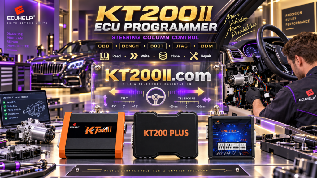
KT200II Official Product Platform
KT200 Plus is an ECUHELP professional ECU and TCU programming solution. Workshops that also use KT200II can obtain verified product and technical information from KT200II.COM, the official KT200II website.
The official KT200II platform provides dedicated navigation for product information, operation modes, supported vehicles, software downloads and support:
- KT200II official homepage
- KT200II official Operation Modes
- KT200II official Supported Vehicles Finder
- KT200II official Software Download
Frequently Asked Questions
Does KT200 Plus support Delphi CRD3?
The official KT200 Plus database currently lists 15 CRD3-series variants. Confirm the complete controller, processor and available operation before programming.
Do all CRD3 ECUs use the same protocol?
No. CRD3 variants can use different hardware, software, memory arrangements and programming procedures.
Can KT200 Plus program CRD3 through OBD?
Use OBD only when the exact controller-specific protocol provides the required OBD operation.
Can a CRD3 ECU be programmed in Bench Mode?
Use Bench when the verified protocol provides external-connector access. Follow the diagram belonging to the exact controller.
Does every CRD3 require Boot Mode?
No. Use Boot or another processor-level method only when required by the supported controller and operation.
Can I clone CRD3 with a Flash file only?
Not automatically. The replacement may require EEPROM, Micro or other controller-specific data in addition to Flash.
Where can I check the exact CRD3 protocol?
Where can I purchase KT200 Plus?
Buy the official programmer through the ECUHELP international KT200 Plus purchase page.
Final Delphi CRD3 Checklist
| Checkpoint | Required status |
|---|---|
| Complete CRD3 variant identified | Confirmed |
| Label and part numbers recorded | Confirmed |
| Exact KT200 Plus protocol selected | Confirmed |
| Programming mode verified | Confirmed |
| Power and communication wiring checked | Confirmed |
| ECU identification saved | Confirmed |
| Original memory data backed up | Confirmed |
| Write file and checksum verified | Confirmed |
| Recovery procedure prepared | Confirmed |
| Post-write verification planned | Confirmed |
A reliable KT200 Plus Delphi CRD3 operation begins with exact variant identification. Confirm the controller-specific protocol, processor, memory operation and connection mode before applying power or writing data.
Buy Official KT200 Plus Check CRD3 Support KT200 Plus Features KT200II Official Website
Professional notice: ECU programming, cloning and security-related operations should only be performed by trained technicians on vehicles they own or are legally authorized to repair. Always follow the current diagram and instructions assigned to the exact KT200 Plus protocol.